(Unifinished article)
Introduction
For my graduation year as an electronics technician, I chose to focus on the design and development of a multiplayer hardware console. My interest in real-time network communication from baremetal hardware drove me to undertake this project, which was completed as part of my graduation requirements. It would be wise to keep in mind that this was done at school, with time and ressources constraints, making it more of a proof of concept than a finished product.
In this post, I will delve into the technical and “creative” considerations that went into the creation of the console. From hardware and software requirements to user experience.
Project description
The project consists of a game streaming network system. It is composed of two devices that can be considered game consoles, each with 6 buttons and 1 analog stick. These two consoles are then connected to the same network, on which a server will obtain the user inputs from the two consoles and compute the live game position of the game. The server will then generate an instantaneous “image” of the game and send it to the two consoles simultaneously, which will then display this “image”. This allows for a multiplayer gaming experience. This streaming method is based on the principle of cloud computing, which allows the computationnal load to be transferred to an external server rather than the console. This technology allows, with relatively limited hardware, to play games that would not have been possible to run otherwise. This approach also allows for centralization of development on a single platform without having to modify the consoles: the hardware and software of the consoles remains the same, changes are made on the server side.
Analysis
Fast Diagram
Synoptic Schematics
Bloc Schematics
Modules
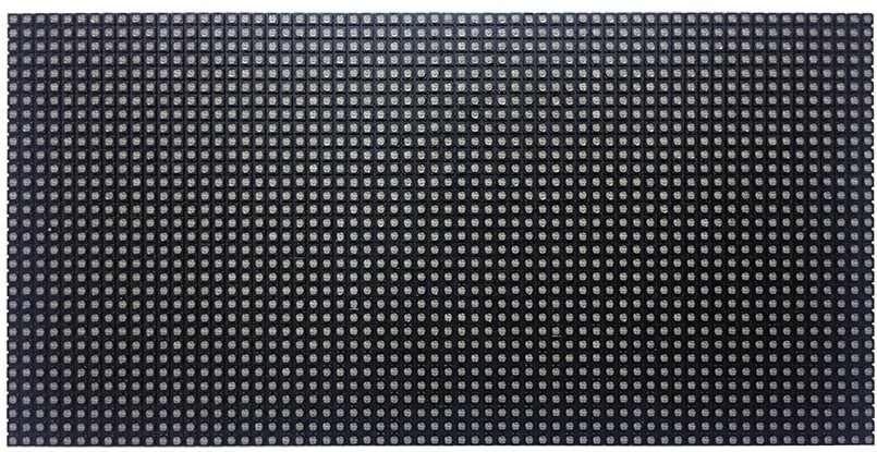
64x32 RGB LED Matrix
The game or menus will be displayed on an 64x32 LED matrix, I chose a low resolution to be able to send the pixel data without compression nor any other heavy processing on the server side. That would have generated an additional load on the console side. I also chose to send the whole pixel data and not only the game data because that would have requiered a different software on the console. In my case the software of the console is dissociated of the game being played because it’s only displaying the pixels as it receives them. The Matrix would allow to play some simple or retro games.
- 64x32 LEDs
- Pitch 2.5" (gap between LEDs)
- HUB75 Normalized connector
- Pixel density 160’000 dots/m^2
- RGB Colors
- Scanning Rate 1/16
Matrix Front
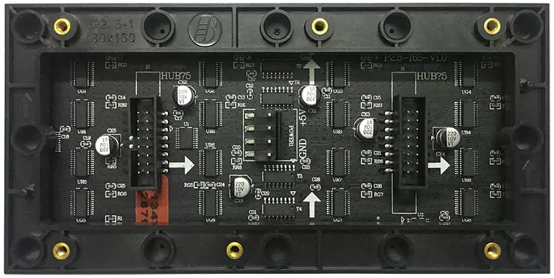
Matrix Back
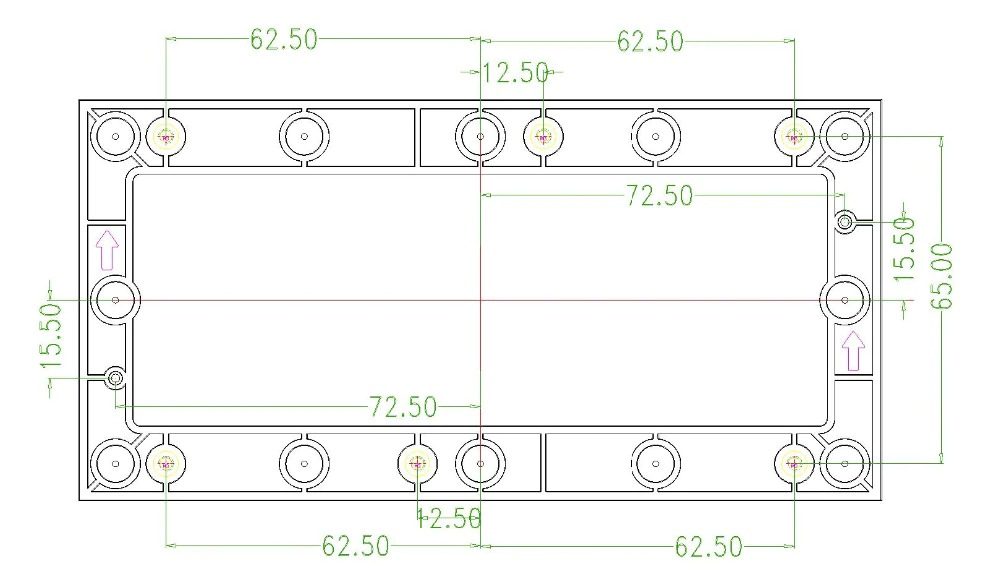
Matrix dimensions
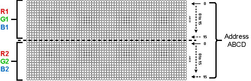
Matrix disposition
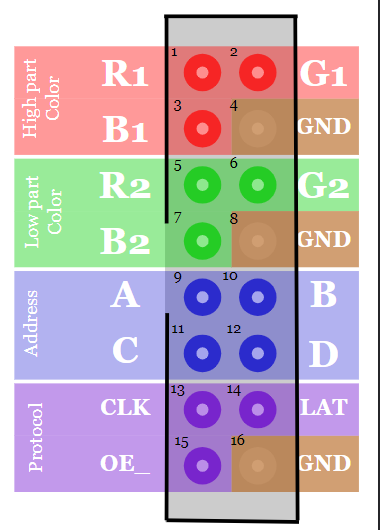
The matrix is divided into 2 parts:
- High part colors are controled with R1, G1, B1 pins
- Low part colors are controled with R2, G2, B2 pins
Only one row can be on at the time, thus we have to address which row we want to turn on with the Adress pins A, B, C, and D.
The 4 address bits will chose the row from 0 to 15 (0b0000 to 0b1111). Both high and low part row are selected by the the same ABCD pins and each chose their colors with their respecting R, G and B pins.
General matrix layout
Matrix pinout
An 8x02 connector (HUB75) is accessible to communicate with the matrix, the Pinout of the matrix can change depending on the type of matrix. In our case, the matrix has a scan rate of 1:16, which means that the number of address bits is 4 (ABCD). These address bits select the row to be displayed, in fact, they choose one line on the top part and the corresponding line on the bottom part. Therefore, there will be 2 lines displayed at the same time.
Matrix Pinout
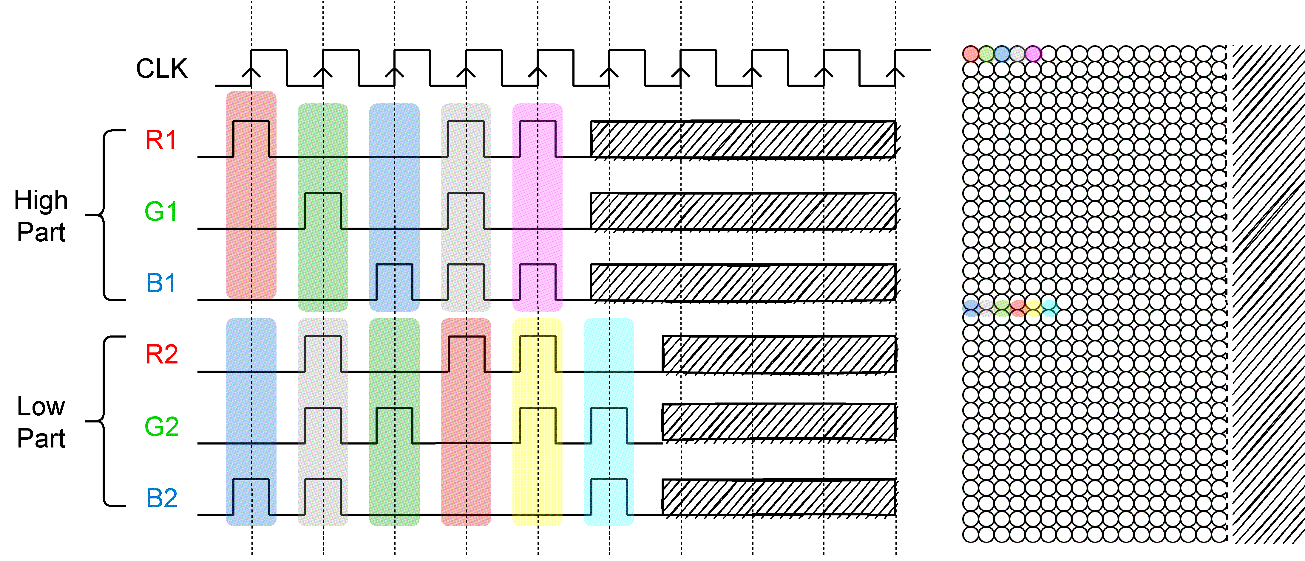
Color selection
The LED matrix being RGB, we can chose each pixel’s color. These colors are independant for the high and low part.
RGB Timings
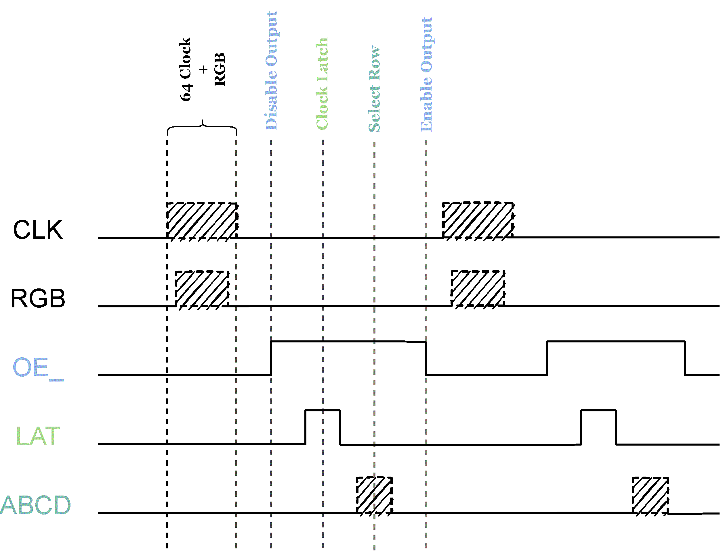
Displaying a row
The process to show a single row (per Part):
- Chose the color with the RGB1 and RGB2 pins (0 or 1 TTL)
- Turn the LED off (output enable to 1 because it’s active low)
- We validate the color of a single LED with the latch pin (This will push the bits into shift registers)
- We select the address of the row we want to show the color on
- We reactivate the LEDs with the output enable (to 0 because it’s active low)
Timing Diagram Row sender
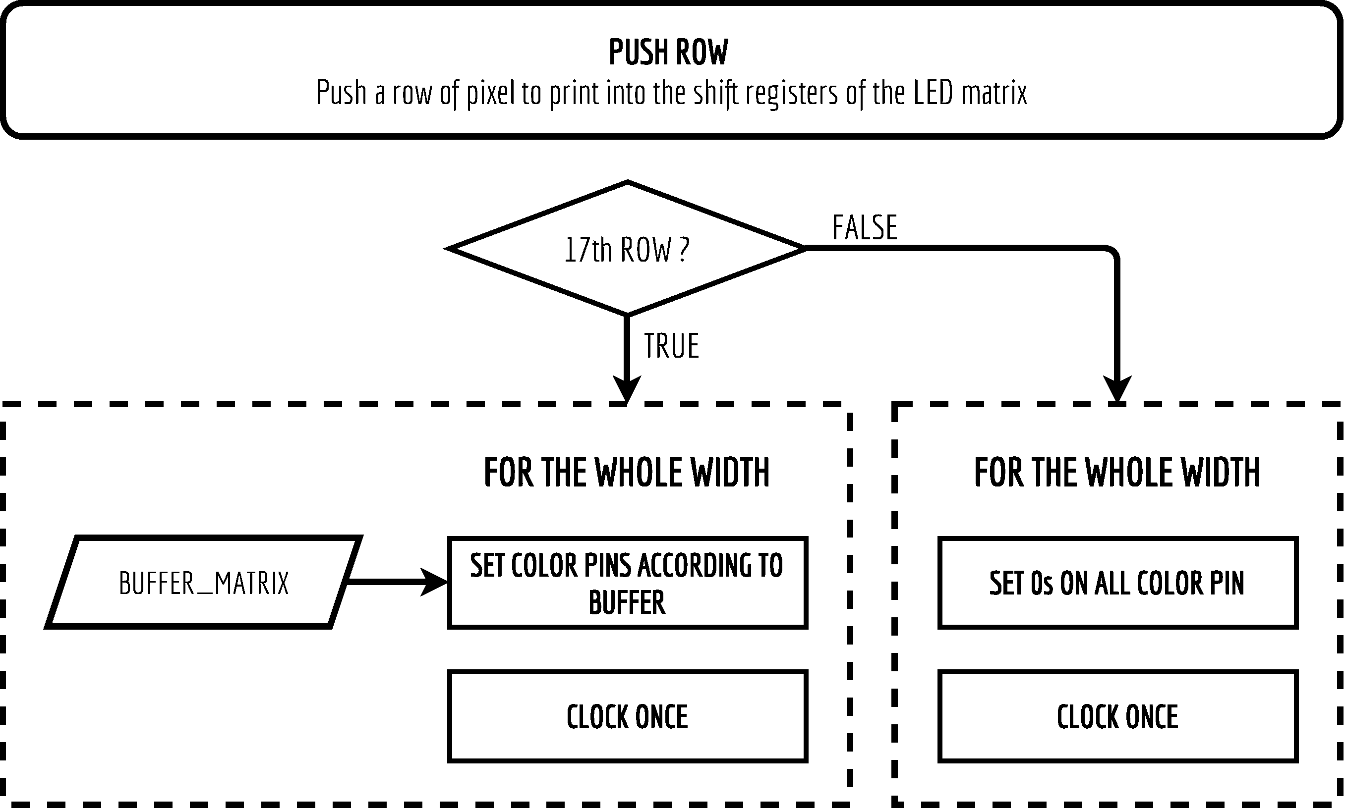
The code for pushing a full row (the buffer pBuffer is global in this example):
void push_row(unsigned char row)
{
   #define MSK_CLEAR 0x03
   unsigned char col = 0;
   unsigned char temp;

   if(row == SCAN_RATE)
   {
      temp = P1 & 0x03;
      P1 = temp;
      //Send zeroes after last line to avoid stronger last line
      for(col = 0; col < WIDTH; col++)
      {
         //Clock one pixel
         CLK = 1;
         CLK = 0;
      }
   }
   else
   {
      for(col = 0; col < WIDTH; col++) //for th whole width
      {
            //Select the color bits
            temp = P1 & 0x03; //clear color part
            temp |= *(pBuffer + row * WIDTH + col); //Set value from buffer
            temp &= ~MSK_CLEAR;
            P1 = temp;
            //Clock one pixel
            CLK = 1;
            CLK = 0;
      }
   }
}
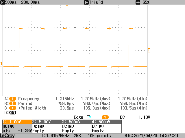
We can see that pushing a single row takes an average of 134 us. The measure has been taken on an oscilloscope by raising a debug pin at the start of push_row() and lowering it at the end.
Measurement Row sending
Displaying a full buffer
We can now display a full row, so we should be able to display a complete buffer by iterating over every rows of the buffer and showing them. In order to see every rows with the same intensity, they will have to be lit a fixed time. So i’ll have to setup a Timer interrupt to trigger the row counter increment. For a smooth displaying on the LED i chose a refresh rate of 100 fps, or 100 Hz. Lines are sent 2 by 2 (High and low part). Therefore 16 lines must be sent to refresh the whole matrix. This means 16 lines must be sent 100 times / second.
Number of time per second we need to show a full row: $$ 100 \cdot 16 = 1600 \frac{row}{second} $$
Time between each row send (Overflow Timer): $$ T = \frac{1s}{1600Hz} = 625 us $$
Timer 0 configuration:
- 16 bits
- Sysclock @ 48 Mhz
- Prescaler @ 48 -> 1 Mhz
- T = 625 us
Loading value of the timer: $$ LV = 2^{16} - \frac{1}{1Mhz} * 625 = 64'911 = 0xFD8F $$
Push row matrix
Timer overflow routine that refreshes the whole matrix
void refresh_matrix() interrupt 1
{
   static unsigned char row = 0;
   pushRow(row);
   OE_ = 1;             //disable LEDs to latch
   Adressage(row);      //set ABCD
   LAT = 1;
   LAT = 0;
   OE_ = 0;  //enable LEDs to show

   if(row < SCAN_RATE){row++;}
   else{row = 0; gFlagBufferPrinted = 1;} //Whole Matrix drawn

   TH0= TIMER0_LOADVALUE_HIG;       // Charge la valeur initiale
   TL0= TIMER0_LOADVALUE_LOW;
   TR0 = 1;   // Start le timer 0
}
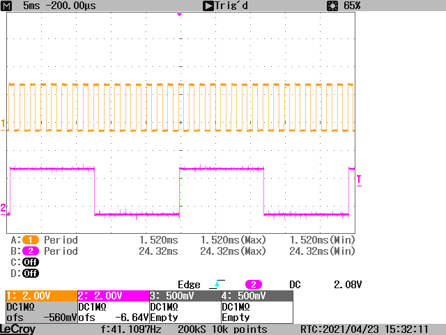
I’ve taken measurements to figure out the real time to display a full buffer. The purple debug pin is reversed each time the full buffer has been displayed. We can see an average of 11 ms for the complete buffer. We can also see that for each buffer, 16 rows are sent.
Mesearued Times for complete buffer display (In purple) and rows (In Orange)
Micro-Controller 8051 F38C
General description
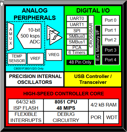
This microcontroller, designed by Silicon Labs from the C8051 F3XX family, is widely used in our school and has a range of development boards to easily program and prototype systems. The microcontroller contains an Intel 8051 processor and several internal peripherals.
- 3 GPIO Ports - 8 bits - 24 IO
- 6 Timers
- 2 hardware UART
- 2 hardware SMBUS (I2c)
- 2 SPI hardware
- 1 Programmable Counter Array - PCA
- 2 external interrupts
- 1 ADC - Multiplexable on multiple GPIO
- 64 kB Flash
- 256 Bytes RAM
- “external” 4096 Bytes XRAM (Slower than RAM)
General Overview of the 8051F38X
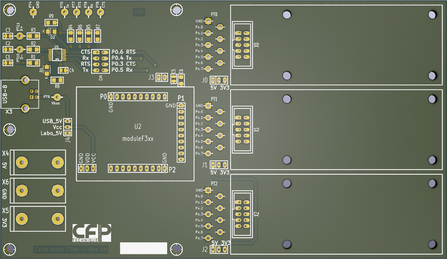
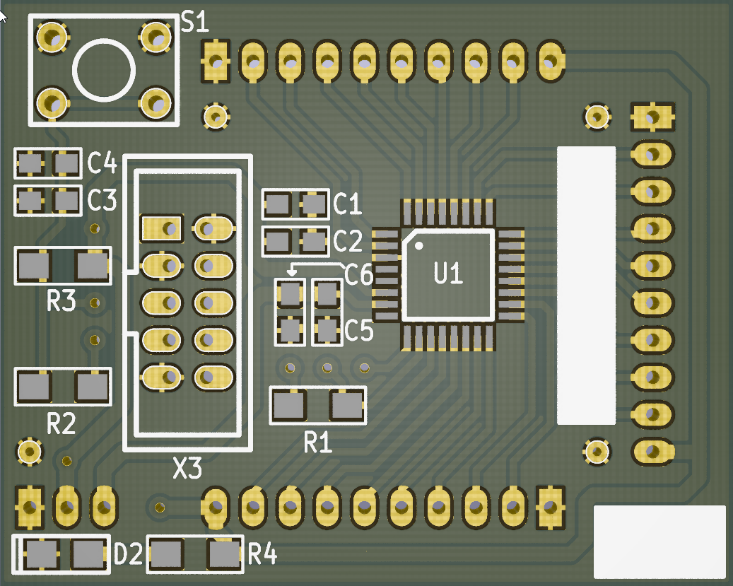
The school provides us with a motherboard on which we can connect “daughter” cards to each of the 3 IO ports. These “daughter” cards can be designed using a Base model. This motherboard contains a microcontroller card that contains the microcontroller itself as well as the circuitry for resetting and programming it. The advantage of this microcontroller module is that a development phase can be done on the card and then it is simply a matter of implanting the card on a more specific circuit to make it work.
3D View of Main developpement Motherboard
3D View of Microcontroller PCB
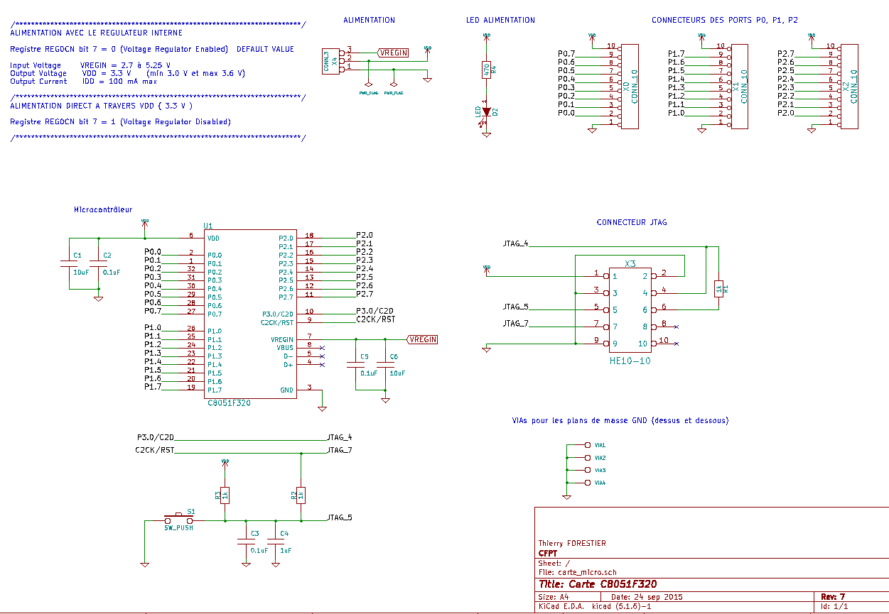
Main dev board schematics
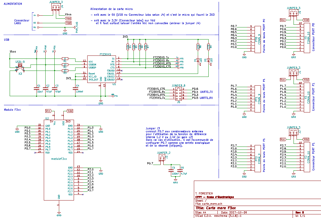
Main dev board schematics
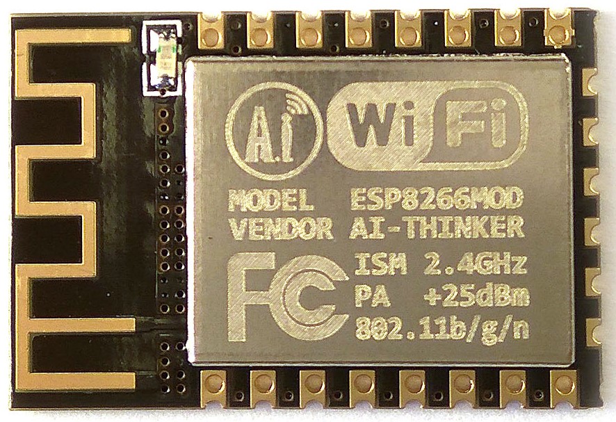
Wifi module - ESP9266 Micro-controller
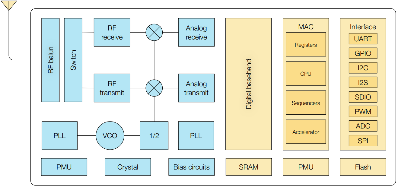
Espressif ESP8266
In order to allow a wifi inter-connectivity, I decided to work with a Espressif micro-controller including a whole Wifi stack, allowing the management and communications through wireless network.
- Up to 160Mhz
- Hardware SPI, UART, I2C etc.
- ADC
- 17 General Purpose Inputs/Outputs - GPIO
- Wifi support - 802.11 b/g/n
- WPA/WPA2 encryption support
Functionnal bloc schematics ESP8266
Physical view of the front
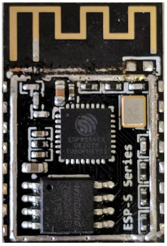
Internal view of the front without the shielding
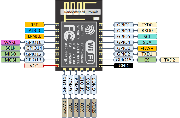
Pinout ESP8266
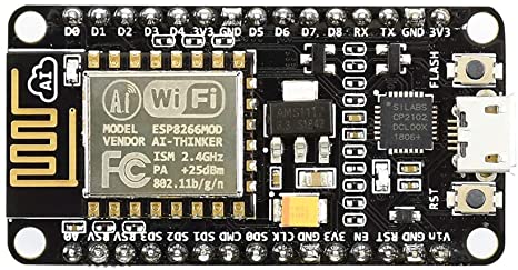
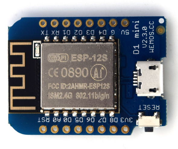
Dev Board
Development boards for the esp8266 are available on the internet, they allow for easy connection using dupont cables or a breadboard. They generally contain a voltage regulator and a USB port that allows the esp to be powered and programmed through a USB-UART or FTDI interface. I have personally used two different boards: a Node MCU and a Wemos D1 mini. These two boards have relatively similar functionality and their main difference is their size.
Node MCU
Wemos D1 mini
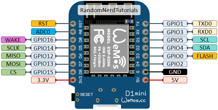
Pinout Wemos D1 mini
Workflow - Micropython
The esp 8266 can be programmed in different languages, using the SDK provided by the manufacturer or using IDEs such as Arduino or Platform IO. In my case, I decided to develop in Micropython.
Description of Micropython:
Micropython is an implementation of the Python programming language optimized to run on a microcontroller. It allows the use of a portion of the Python libraries directly on a microcontroller such as the esp8266 being used.
Installation of Micropython:
It is quite simple to install micropython, just download a tool called esptool.
pip install esptool
This tool will allow us to erase ESP’s memory and upload the micropython needed firmware.
We need to:
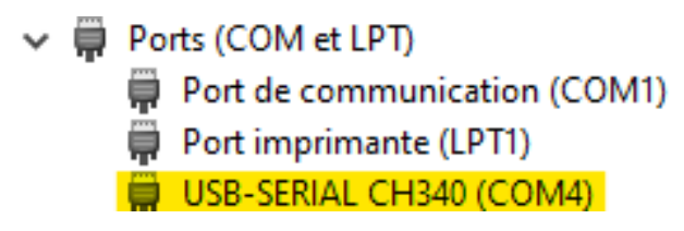
- Plug the board
- Check the COM port number
Com port
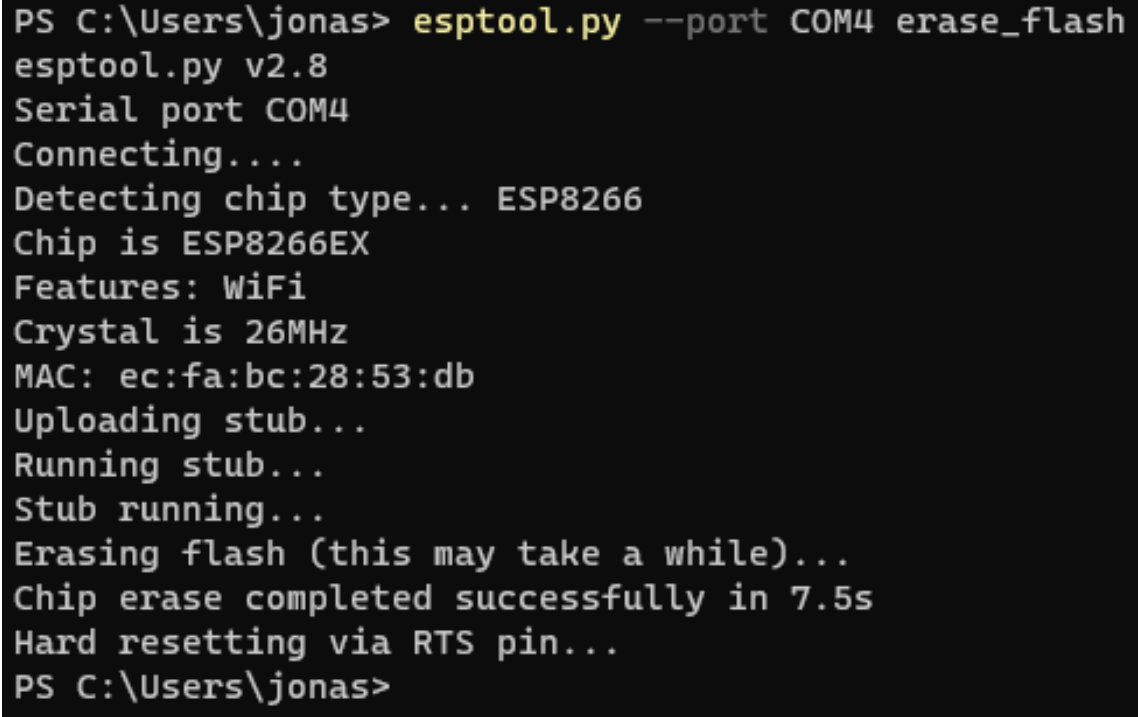
In a terminal, you need to erase the flash of the ESP:
esptool.py --port COM4 erase_flash
Console output erasing
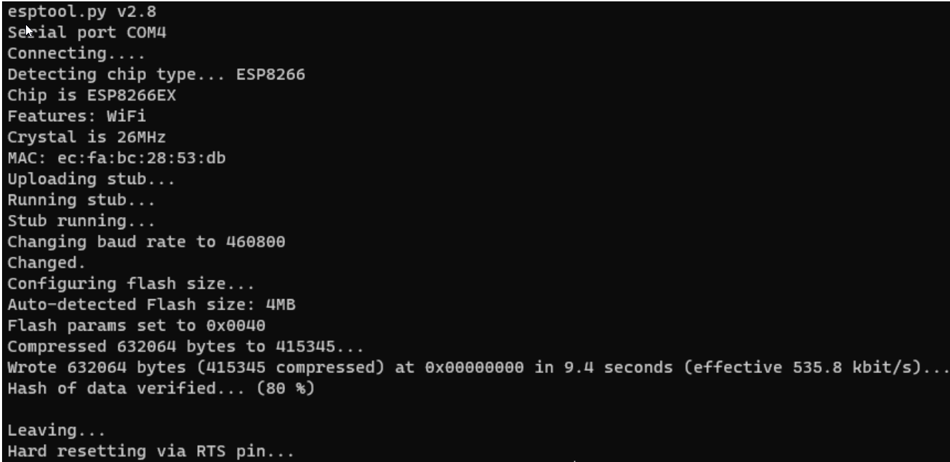
Next, you will need to download the micropython firmware adapted to the microcontroller you want to program on the official micropython.org website. In my case, I took version 1.14 adapted to the esp 8266. To install the firmware, enter this command in a terminal (esp8266[…] .bin being the file path to the previously downloaded binary file).
esptool.py −−port COM4 −−baud 460800 write_flash −−flashsize=detect 0 esp8266−20170108−v1.14.bin
Console output Micropython firmware install
Using Micropython REPL
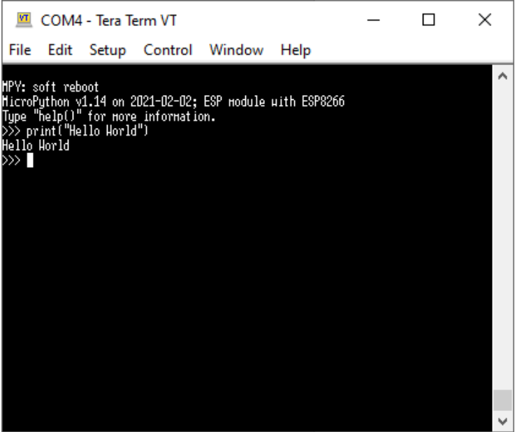
After installing micropython, it is possible to test python in a terminal via a serial connection. To do this, you need to:
- Open a terminal emulator such as Teraterm
- Select the COM port for connecting to the ESP
- Configure a speed of 115200 (Default for micropython) We are then connected to an interactive REPL in which it is possible to test commands, as we would on a python instance on a PC. It is also possible to reset the board with Ctrl+d.
Live Interactive repl
Send files to the board
Although it is already possible to interact with the board using the Live REPL described earlier, it is desirable to be able to program on a PC editor and upload a program once it is finished. There are several solutions for this. However, I will write about the one I used (using Adafruit ampy).
Files can be added to the board’s memory, and a certain name can be given to force a sequence:
- The boot file runs when the board is launched
- The main file runs when the boot file has finished running
- The main file can call or launch other files on the board.
Files can be sent in several ways, and tools such as Mu or uPyLoader can be used to send the files. I decided to use Ampy due to its simplicity of installation, use, and clear documentation, it offers one of the fastest and simplest ways to access a board containing micro-Python.
Using Adafruit AMPY
esptool.py −−port COM4 −−baud 460800 writeflash −−flashsize=detect 0 esp8266−20170108−v1.14.bin
Ampy is a tool that can be used in the terminal, there are various commands: In a terminal (PORT being the port in the device manager)
Using Adafruit AMPY
ampy −−port {PORT} {COMMAND} {ARGUMENT}
Available Commands
- get : Get the files from the board
- ls : List files on the board
- put : Add a file on the board
- rm : Delete file from board
- run : Run a file directly on the board
Server - Raspberry pi 4
General overview
The Raspberry PI is a Single Board Computer developed by Raspberry, it is a board containing everything needed to run an operating system, manage inputs and outputs, and everything else needed to qualify it as a computer. I chose to use the Raspberry Pi 4 as a server in my system because it is small, relatively easy to set up, and powerful enough to perform all kinds of tasks.
- Raspberry Pi 4 Model B
- 4 GB of RAM
- Quadcore Processor - ARMv8
- USB C Power - need 15W
- 1 Gb Ethernet Port
- Micro SD Memory Slot
Raspberry pi photo